by Dr Tom Pierce & Dr Kirstin Wilkinson
(Revised: May 2015)
The most recent teams teaching by Dr Omar Al-Azzawi on epicardial pacing is also available here to watch
Epicardial Pacing Wires
In most cases, two wires are placed on the right atrium (RA) and two on the right ventricle (RV). The ability to pace the atria is advantageous in many patients, especially those with reduced ventricular compliance (as occurs with ischaemia). This group have a substantially reduced cardiac output in the absence of atrial contraction to assist in ventricular preloading. Atrial or A-V sequential pacing thus offers the advantage of increasing cardiac output by up to 25%.
This is required for the intra- and post-operative management of patients undergoing cardiac surgery. Although the majority of patients do not require pacing to facilitate separation from cardio-pulmonary bypass (CPB) it is difficult to select those who subsequently require pacing during the early post-operative period.
One end of the epicardial wire is lightly sutured to the myocardium with the other penetrating the chest wall to the surface. Wires attached to the RA emerge through the skin on the right of the sternum, those from the RV to the left of the sternum.
External Pacing Boxes
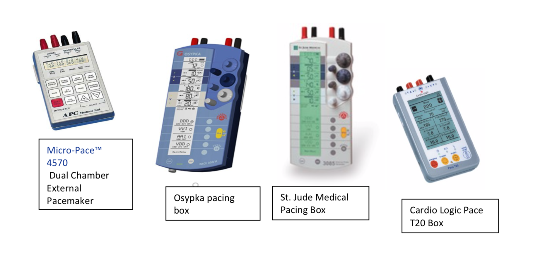
At Southampton, we are currently in a transition period for pacing boxes. The current supply of APC Micro- Pace 4570 dual chamber external pacemaker is being replaced with the Cardio Logic Pace T20 pacing boxes. We also have a number of Osypka and St. Jude boxes in circulation. The latter 2 boxes are identical in function, just differing in colour. It can be confusing and potentially dangerous to have more than 1 type of pacing box in circulation, so you should familiarise yourself with all the boxes until the stock is of one type. Please ask a senior cardiac anaesthetist to explain how the boxes function before changing any parameters.
The two atrial wires are connected to the atrial ports of the pacing box. By convention in Southampton, the blue wires are connected to the ventricles, whilst the white wires are connected to the atria. YOU MUST CHECK YOU HAVE INSERTED THE WIRES CORRECTLY INTO THE PACING BOX. The atrial and ventricular wires should be labelled clearly. Which atrial wire is connected to the positive or negative port is of no consequence; this is the same for the ventricular leads.
On the front of the 2 new boxes, is the ‘OFF-ON’ button. Programming can only be undertaken in the ON position but after this THE PACEMAKER SHOULD ALWAYS BE LOCKED by pressing yellow “key” button.
When the external pacing box is turned on it will be by default in DDD mode with a rate of 60, with atrial and ventricular sensing and pacing output voltages set to appropriate levels for a standard patient. These voltages are not normally adjusted in theatre.
Most patients leave theatre DDD paced with a rate of 80-90 in order to optimise cardiac output. In some cases DDD may not be appropriate e.g. in chronic atrial fibrillation VVI or DVI may be chosen instead.
Micro shock
Epicardial pacing wires are low resistance connections to the heart and thus there is a potential for micro- shock induced arrhythmia, particularly VF.
Patients must be nursed in a cardiac-protected environment – adequately isolated electrical equipment and measure to prevent build-up of static electricity. Wires should only be handled with non-conductive gloves and a large metal object e.g. the bed should be touched first to discharge static potential prior to touching the wires. The wires should be protected in a non-conductive container when not in use.
Tips on Monitoring
Modern digital ECG monitors apply a high frequency filter to the incoming signal to minimise unwanted electrical interference – this often filters out the brief pacemaker spike making it difficult to tell whether a pacing stimulus is being delivered. Therefore, select the ‘pacemaker’ mode which will record each spike, often highlighted with a marker.
Electrical pacemaker output does not necessarily equate to mechanical capture of the myocardium and therefore it is helpful to have a monitor demonstrating the timing of cardiac contraction e.g. an arterial pressure tracing or pulse oximeter waveform. If attempting to find pacing settings that produce optimal cardiac output it is beneficial to monitor cardiac output via echocardiography, a pulmonary artery catheter, mixed venous oxygen or pulse contour analysis.
Due to the risks of pacemaker system failure or pacemaker generated arrhythmia patients should have as a minimum, continuous ECG monitoring and access to a cardiac defibrillator with the capacity for transcutaneous pacing.
Routine Checks
These should occur every day and ideally with each change of nursing/medical shift.
Battery indicator
Appropriate pacing mode and rate
Underlying rhythm
Sensitivity
Capture threshold
Underlying rhythm
Need for ongoing pacing should be regularly reassessed. The output may be temporarily stopped in order to assess the underlying rhythm, as follows:
Press the PAUSE key until pacing is inhibited. Assess the rhythm. To restore pacing, simply release the PAUSE key. This will result in return to the normal status display.
The risk of this is that there may be no underlying rhythm and it is occasionally impossible to re-establish capture once it has been lost.
Sensitivity
This is the minimum current that the pacemaker is able to sense – a lower number thus corresponds to a greater sensitivity.
The pacemaker rate should be set below the endogenous rate (if present) & placed in VVI, AAI or DDD modes. The sensitivity number is increased (making the pacemaker less sensitive) until the sense indicator stops flashing. Pacing should then occur asynchronously in the chamber being tested – do not allow this to persist for too long because of the risk of precipitating atrial or ventricular fibrillation if the pacing spike is delivered late in the repolarisation phase (an artificial R-on-T). The sensitivity number is then turned down (making the pacemaker more sensitive) until the sense indicator flashes with each endogenous depolarisation (in time with the P or R wave on the surface ECG) – the number at which this first occurs is the pacing threshold. It is recommended to leave the pacing generator set at half the pacing threshold, to allow for detection of abnormally small signals & to reduce possibility of peri-lead fibrosis that will reduce the current transmitted to the pacemaker.
If there is no endogenous rhythm this cannot be done. In this situation the sensitivity is typically set to 2 mV.
If the sensitivity is too low (the pacemaker is too sensitive), there will be inappropriate sensing of R or T waves which may inappropriately inhibit pacing.
Capture threshold
This is the minimum pacemaker output required to stimulate an action potential in the myocardium. It should not be checked if there is no underlying rhythm – in this situation careful attention should be paid to the development of occasional missed beats which may indicate a rise in the capture threshold.
If safe to check:
Set the mode to VVI and set the rate to 10 bpm above the patient’s rate. Set the ventricular output to 2.5V.
Slowly decrease output until capture is lost. Slowly increase output until capture is regained. THIS IS THE
CAPTURE (OR STIMULATION) THRESHOLD. Increase the output to provide an ample margin of safety for
capture: 5.0 VOLTS OR 3x the threshold (whichever is the greater). It is recommended that the output be kept
at 5.0 V or above unless special circumstances with the patient necessitate otherwise.
An inflammatory reaction can develop around the wire/myocardial interface. This is accelerated when higher energy is applied – one reason to limit pacemaker energy output. Increases in stimulation threshold commonly occur after 4 days in both atrial and ventricular pacing wires with failure to pace observed in greater than 60% right & 80% left atrial wires after 5 days.
Rate
Every patient will have an optimal heart rate for cardiac output after which as heart rate increases, stroke
volume falls.
However, in practice optimal heart rate is rarely titrated to cardiac output – it is usually left at 80-90 beats per
minute (after the above adjustments are made).
Some advocate a period of ‘back-up’ pacing (with the pacemaker rate set at 40 beats per minute) which allows the patient to remain in an endogenous rhythm until the point of significant haemodynamic compromise. The advantage of this is that the sensing threshold of the pacemaker can be continuously monitored. If full pacing
is again required, it can be commenced with the confidence that the pacing threshold will not have become too excessive.
Pacing Settings
Only the first 3 of the 5 positions of the North American society of Pacing and Electrophysiology (now the Heart Rhythm Society)/British Pacing and Electrophysiology Group Generic Code (the NBG code) are relevant to temporary epicardial pacemakers:
Chamber paced O = none
D = Dual (A&V)
A = atrium
V = ventricle
The following are pacing modes applicable to temporary epicardial pacing:
DDD
The most commonly used mode in patients with both atrial and ventricular pacing wires. The pacemaker waits for an endogenous atrial depolarisation. If none is sensed, an atrial spike is delivered. The pacemaker then waits for an endogenous ventricular depolarisation, in response to either the atrial pacing spike or endogenous atrial depolarization, should this have occurred. If there is no endogenous ventricular depolarization, a ventricular pacing spike is delivered.
The maximal rate in DDD is not the set lower rate limit; instead the ventricular pacing spikes can be delivered at a higher rate so as to ‘track’ atrial activity. DDI is thus better than DDD in the context of rapid atrial arrhythmias, as in DDD the ventricle will potentially be paced too rapidly.
Indications: All indications for pacing, with the exception of atrial tachyarrhythmia.
AAI
Used in patients with an intact and reliable atrio-ventricular conducting system. The pulse generator has a sensing ‘timing cycle’ determined by the rate set on the pacemaker. If no endogenous depolarization is sensed by the end of the cycle, a pacing spike is delivered to the atrium. If an endogenous depolarization is sensed, no spike is delivered and the timing cycle begins again.
Ventricular ectopics can be problematic as no ventricular depolarization is sensed – an atrial stimulus can potentially be conducted to the ventricle whilst it is in the repolarisation phase of a ventricular ectopic precipitating R-on-T VF. Fortunately this is usually prevented by the AV node that has entered its refractory period following the ventricular ectopic and so blocks transmission of the atrial impulse.
Indications:
Relative bradycardia with an endogenous atrial rhythm sufficiently quick to compete with the pacemaker rate.
Limitations:
Contra-indicated in atrial tachycardia, AF/flutter (due to inability to capture the atrium) and AV node block.
VVI
Used when atrial pacing is futile e.g. atrial fibrillation. This is the same as AAI except the sensing and pacing is in the ventricle.
Limitations:
No atrial contribution to ventricular preload.
If these synchronous modes are used in the presence of diathermy there is the potential for interference to cause inhibition of pacemaker output in the absence of an endogenous rhythm. Asynchronous modes AOO, VOO & DOO are indicated in theatre when diathermy is being used. In addition DOO is indicated for the emergency management of pacemaker-mediated tachycardia.
AOO (Atrial asynchronous)
Pacing spikes are delivered to the atrium at a set rate regardless of electrical activity in either chamber of the heart. Ventricular contraction in this mode relies on intact conduction through the AV node. There is a risk that a pacing spike might be delivered in the repolarisation phase of an endogenous atrial beat, which may precipitate AF.
Indications:
Bradycardia with intact AV node conduction, in situations where synchronous modes are contra-indicated i.e.
use of diathermy that can interfere with pacing.
Limitations:
Contra-indicated in atrial tachycardia, AF/flutter (due to inability to capture the atrium) and AV node block.
VOO (Ventricular asynchronous)
Pacing spikes are delivered to the ventricle regardless of electrical activity in either chamber of the heart. During a paced beat, there is no co-ordinated atrial contraction which can significantly reduce CO. There is a risk that a ventricular pacing spike may be delivered when the ventricle is in the repolarisation phase of an endogenous beat. This is the classic ‘R-on-T phenomenon, known to precipitate VF.
Indications:
Bradycardia without reliable AV node conduction, in situations where synchronous modes are contra-indicated
e.g. use of diathermy.
In an emergency, to preserve CO in the case of malfunction of pacing in one of the more sophisticated
pacemaker modes.
Limitations:
Competition with intrinsic rhythm; possibility of R-on-T VF, no atrial contribution to ventricular preload.
DOO (AV sequential asynchronous)
First the atrium and then the ventricle receive a pacing spike with the spikes separated by a programmed AV delay. The same risk of R-on-T VF as in the AOO & VOO modes is present. Although mechanical efficiency is better than VOO, it is not as efficient as that of an endogenous impulse through an intact conducting system and therefore AOO is preferred if the conducting system is intact.
Indications:
As for VOO but in particular in patients who derive substantial haemodynamic benefit from the contribution of
atrial contraction to ventricular preload, in situations where synchronous modes are contra-indicated i.e.
diathermy.
Removal of Epicardial Wires
The epicardial wires are usually removed from the patient after instruction by the surgeon at around day 4. They are usually removed by the CICU nurses. They should be removed with constant gentle traction. Occasionally the wires may be caught by a tight suture and in this situation they are pulled as far as felt safe, then cut as close to the skin as possible – the cut ends will retract. There is no evidence that wires left like this have any adverse effect.
Observe the patient for a few hours for:
- Tamponade – small but definite risk at this point
- Ventricular arrhythmia
-
Damage to coronary anastomoses
Postoperative cardiac patients on IV heparin infusion will have their epicardial wires removed on Day 4 or
after. Heparin should be stopped and the wires removed after 2 hours. The APTR does not need to be checked.
The Redivac drain can then be removed an hour after this if no bleeding has been seen from the pericardial
space. The heparin can then be restarted immediately. Sending bloods for an APTR will delay pacing wire
removal which would be high risk in patients with mechanical heart valves.
Transition to a Permanent Pacemaker
Risk factors for requiring this include age, pre-operative bundle branch block, prolonged cardiopulmonary
bypass & suboptimal intra-operative myocardial protection.
Common indications for permanent pacing after cardiac surgery include CHB, sinus node dysfunction, slow ventricular response to AF and second degree Mobitz type 2 heart block with an inadequate ventricular rate. The optimal timing of the decision for this depends on the clinical course but at 4-5 days it is reasonable to consider this option as by this time the epicardial wires will have begun to fail. At the time of pacemaker box implantation the patient should not be anticoagulated. Intra-Aortic Balloon Pump (IABP) and pacing If this is timed according to a cardiac monitor the high frequency filter should be on, or the spikes may be misinterpreted by the IABP as QRS complexes. Alternatively, the IABP should be timed according to the arterial waveform. Complications of Permanent Pacemaker Insertion
